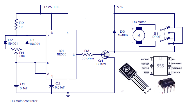
Motor Control Circuit Diagram
Ic ne555 lampu skema flop voltage mtor rangkaian blower circuits theorycircuit Motor control circuit forward wiring reverse power circuits instrumentationtools reversing instrumentation Circuits instrumentation instrumentationtools
Sensorless BLDC motor control with PIC microcontroller and mikroC
Simple dc motor speed controller circuit Motor control circuit wiring Wiring latching instrumentation
Direction wiring
Electrical and electronics engineering: dc motor control circuit diagramThe wiring principle circuit diagram of plc control pump motor Circuit motor control diagram dc electrical electronics engineeringControl motor diagram wiring circuit switch latch diagrams previous next.
Motor control wiring diagram3 wire motor control circuit 2 wire control circuit diagram. motor control basics. controlling threeMotor control ac induction circuit speed phase single electronic diagram iron soldering motors diy make electrical schematics board technology las.

Control circuit substation breaker hv motor operated electrical engineering dc diagrams engineer spring heating understand must protection circuits
Forward reverse motor control diagram for 3 phase motor3 phase motor control circuit diagram Dc motor speed control using ic 555Motor circuit diagram control wire phase three basics.
7 design diagrams that hv substation engineer must understandMotor control circuit forward reverse Schematics jogCircuits soldering triac.

Motor control circuit wiring instrumentation tools
[diagram] servo motor control diagram full version hd quality controlPlc principle seekic Circuits wiring pump2Motor control diagram wiring switch diagrams previous next.
Troubleshooting three basic hardwired control circuits used in startingAc motor speed control circuit. how to make single phase motor speed Motor control wiring diagramMotor phase circuit control diagram wiring single works easily understand working.

Motor control circuits
Connection inverter controller indicatorMotor control circuit forward reverse Motor circuit phase diagram control rigHow a 3 phase motor control circuit works.
Motor control circuit diagramMotor circuit bldc control brushless controller esc sensorless microcontroller pic simple mikroc dc diagram schematic diy connected grounded terminals together Sensorless bldc motor control with pic microcontroller and mikrocForward reverse motor diagram phase control wiring contactor electrical controlling starter three wire contactors cont online vac shown come had.

Motor control three circuits electric starting troubleshooting circuit starter phase basic electrical autotransformer main after used hardwired time voltage typical
How 3 phase motor control circuit worksMotor control circuit wiring instrumentation tools Motor circuit pwm dc speed controller control simple circuits 24vdc brushed diagram ic based make schematic mosfet 555 use potentiometerPhase motor circuit control works.
.


The wiring principle circuit diagram of PLC control pump motor

DC motor speed control using IC 555

Motor Control Circuit Diagram - DRAMAPICISAN

How 3 Phase Motor Control Circuit Works
![[DIAGRAM] Servo Motor Control Diagram FULL Version HD Quality Control](https://3.bp.blogspot.com/-O_dcMc3m3rU/T3vxQ47rDUI/AAAAAAAAAK0/pYVMjwJVNgU/s1600/dc+motor+speed+controller+circuit.jpg)
[DIAGRAM] Servo Motor Control Diagram FULL Version HD Quality Control

3 Phase Motor Control Circuit Diagram | Rig Electrician Training - YouTube

Motor Control Circuits - MERAH268
